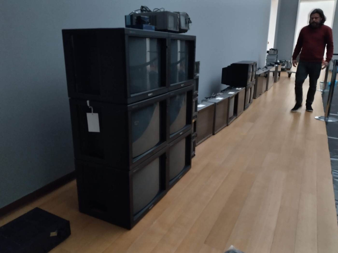
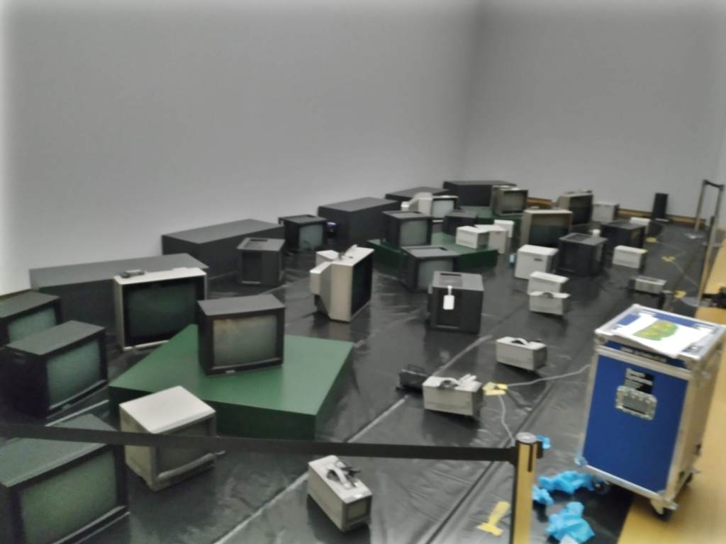
Assembly of the TV garden.
After the rough layout of the monitors to their approximated positions on the floor, it was possible to start pulling power for the monitors. Cabling for power was done in 3 separate groups as the draw is bigger with these monitors. This was all pre-planned by the museum so it was somewhat easy. Connecting the dots so to say.
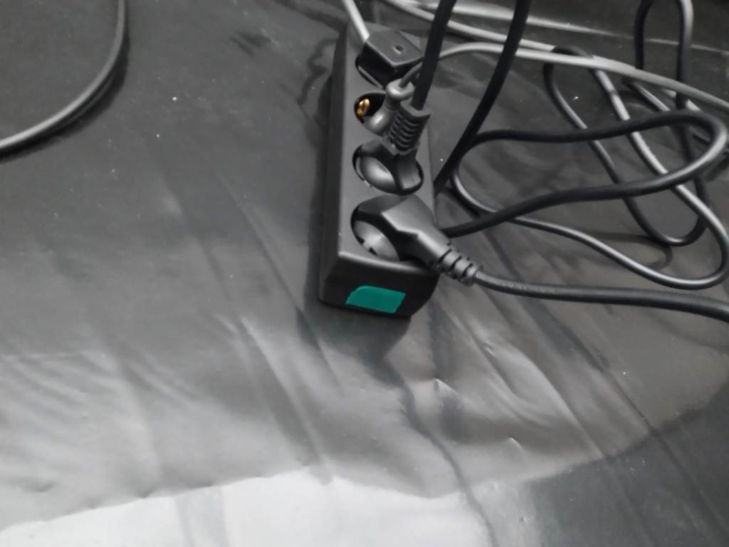
In this cased I made use of 3 different colored electrical tape, on the plans and on the monitors, to quickly see which monitors where still un-powered.
Green group. 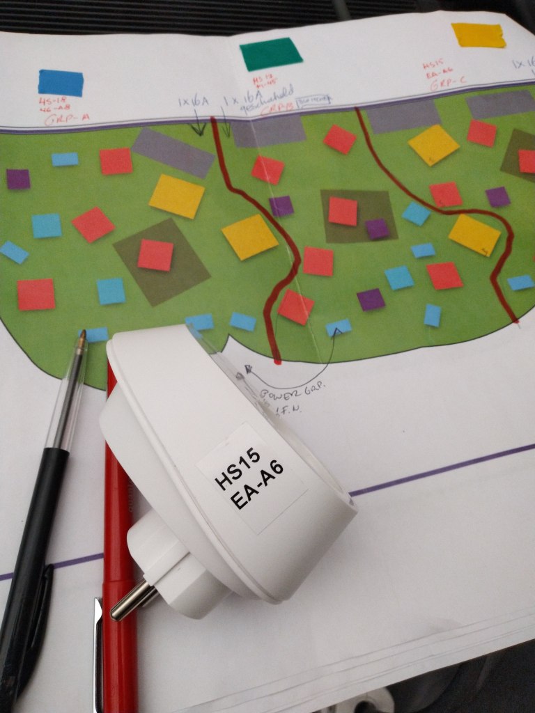
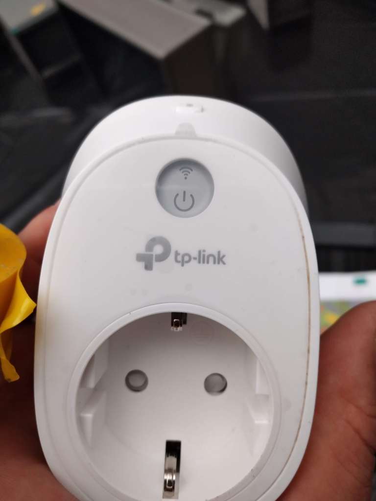
Electrical grouping and the Wifi relay. 
pow
The new thing for me is the usage of Wifi Relays for the equipment. This is a nice idea for remote controlling and scheduling of the power.
As with the powergroups the signal chain is likewise grouped from several outputs from one Cramer-box. Here I stumbled upon some snags as the signal was garbled. It took some time to figure out where the fault was. (A dodgy VGA to Composite-connector from the Brightsign-unit (HD 220).
The signal is daisy-chained from one monitor to another, so this is un-complicated, but there where several monitors that lacked output for the signal, so these where connected to own individual outputs from the Cramerbox starting from the highest numbering going donwards. (16-15-14 and so on.)
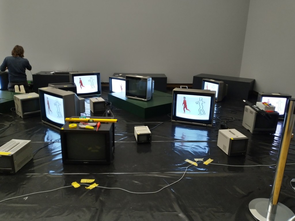
First signs of life. 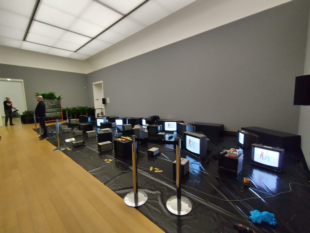

Jätä kommentti